

Aluminium Solar Mounting Profile: OEM Selection Guide
- By:Naview
- Date:2026-10-08
By the NA-VIEW Aluminium Technical Team | 11 years in aluminium extrusion | 8+ years supplying solar mounting OEMs across 30+ countries | ISO 9001 certified manufacturing
A buyer in Málaga wrote to us in November after a winter storm lifted an entire solar array off a south-facing roof. The supplier had quoted the cheapest aluminium solar mounting profile on Alibaba. Twelve modules were off the building, three landed on a neighbouring car. None of the clamps had failed. Instead, the rail had snapped clean through its wall, where the extrusion die had left a 0.9 mm section instead of the 1.6 mm the engineering note called for. This buyer had specs and a sample, but no third-party test report and no factory audit. Between the replacement order, the air freight and the dented reputation, the failure cost ten times what the original saving was worth.
Aluminium solar mounting profile is the metal you forget about after installation. By the time it fails, the whole array is at risk. Aluminium extrusions have become the dominant structural choice for rooftop and ground-mount arrays because of their strength-to-weight ratio, corrosion resistance and the speed at which a dedicated mill can turn around custom sections. What separates a profile that survives 25 years from one that fails in three is a handful of decisions made before the die is cut.
What an aluminium solar mounting profile has to do, which alloys survive at the lowest cost, and the eight quality checks we run on every shipment before it leaves the press is what this guide is for. NA-VIEW has been supplying aluminium solar mounting profile extrusions to module makers and EPC contractors across 30+ countries for more than eight years. The advice below is what we wish every buyer asked first time round.
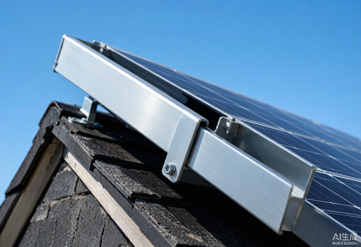
Table of Contents
- Why Aluminium Owns the Solar Mounting Market
- Anatomy of a Solar Mounting Profile System
- Rail, Clamp, Leg, Bracket, Post: The Five Profiles That Make Up an Array
- Alloy Selection: 6063 T5, 6005 T5 or 6061 T6?
- Section Design and Wall Thickness Rules
- Surface Treatment for 25 Years Outdoors
- Wind, Snow, Seismic and Thermal Load Cases
- Standards and Code Compliance Map
- Ground Mount vs Roof Mount vs Carport
- Connection Hardware and Grounding
- Eight Buyer Pitfalls Before You Sign the PO
- NA-VIEW Solar Mounting Profile Capabilities
- Frequently Asked Questions
1. Why Aluminium Owns the Solar Mounting Market
Three properties decide almost every aluminium solar mounting profile material decision, and aluminium wins all three.
Weight. A 6063 T5 aluminium rail at 1.6 mm wall weighs roughly 0.55 kg per metre. The same stiffness in hot-dip galvanised steel comes in at 1.30 kg per metre. On a rooftop, this is the difference between an aluminium solar mounting profile that needs only two M8 fixings per metre and one that needs three. On a ground-mount array it is the difference between a manageable pallet handling job and a crane on site.
Corrosion. Aluminium forms a self-healing oxide skin that protects the metal even when the surface is scratched. Galvanised steel protects itself too, but the moment the zinc is breached, the steel begins to rust. In coastal, agricultural or industrial atmospheres where the air is acidic, aluminium can outlast steel by a factor of three to five before the first structural concern appears.
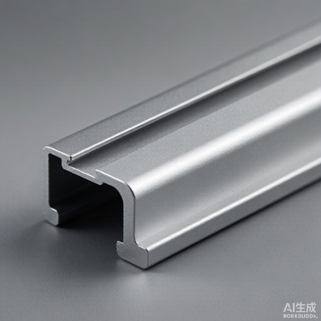
Formability. A custom aluminium solar mounting profile can be extruded in any reasonably sane shape at tolerances tight enough that no machining is needed. Your mounting rail can carry its own click-in clamp channel, water drip groove and pre-punched earthing strap slot all in one extrusion. An equivalent steel profile needs welded brackets, separate clamp strips and post-galvanising paint repairs at every joint.
One downside deserves attention: galvanic corrosion where aluminium meets a dissimilar metal in a wet environment. We will come back to that in the hardware section, because getting this wrong is one of the eight pitfalls and it costs arrays every year.
2. Anatomy of a Solar Mounting Profile System
Most solar mounting structures are made up of the same five parts, repeated across the array. The reason to know each part by name is that you can order different alloys and finishes for different parts without doubling tooling cost.
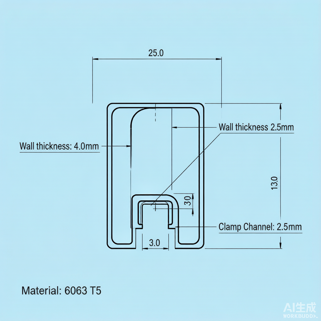
Rail — the long horizontal member to which the modules clamp. Lengths are usually 1.2 m, 2.1 m, 4.2 m or 6.0 m in residential systems, and 12.0 m continuous in commercial ground-mount. A standard rail channel is 40 mm wide with a C-shaped cross-section that accepts either bolt-on or click-in clamps.
Mid-clamp — a small aluminium block sitting between two adjacent modules to hold them both to the rail. Usually 30 to 40 mm long, machined or cast.
End-clamp — the equivalent block at the row ends, where only one module needs to be held. It is the same shape as the mid-clamp with a different outer profile.
Leg or hanger — the L-foot, hanger bolt or roof bracket that fixes the rail to the substrate. Pitched roofs usually take stainless steel hooks under the tiles. Flat roofs call for ballasted plastic feet, whereas ground-mount systems use galvanised steel posts or driven aluminium piles.
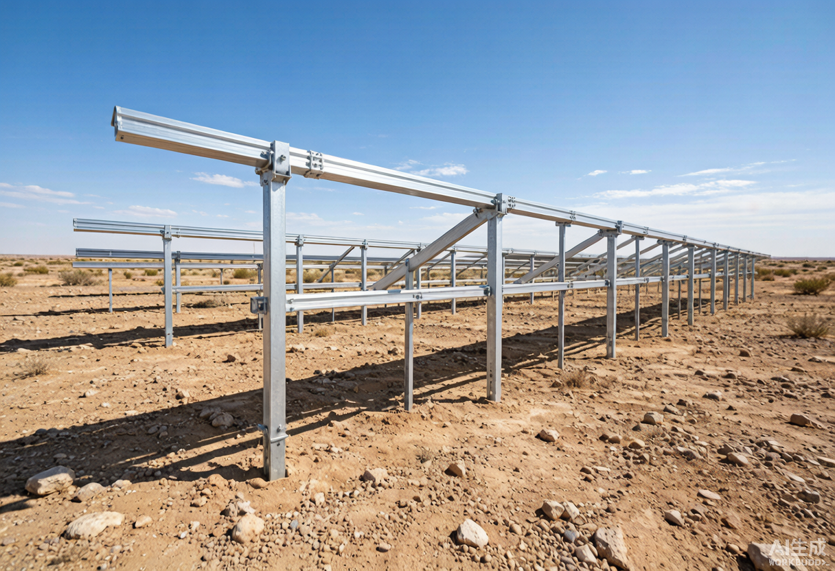
Post and beam (ground-mount only) — the heavy aluminium I-beam or rectangular hollow section that carries the rail above the ground. Posts are typically 1.5 m to 3.0 m above grade, beams 4.2 m to 12.0 m long.
Each of these five parts can be a different alloy and a different finish, and on most NA-VIEW orders they are. The visible rail and clamps carry the cosmetic anodising, while the structural leg and post go mill-finish because they are out of sight.
3. Rail, Clamp, Leg, Bracket, Post: The Five Profiles That Make Up an Array
When you ask a profile supplier to quote an aluminium solar mounting profile kit, expect them to ask which of the five sub-profiles they need. Below is how the typology usually maps to common project types.
| Project Type | Rail | Mid + End Clamp | Leg / Bracket | Post / Beam |
|---|---|---|---|---|
| Residential pitched roof | 6063 T5 AA20 anodised rail, 1.6 mm wall | 6063 T5 mill-finish or anodised | Stainless hook + 6063 T5 L-foot | n/a |
| Commercial flat roof | 6005 T5 AA20 anodised rail, 2.0 mm wall | 6005 T5 anodised | Ballasted HDPE foot + 6005 T5 tilt bracket | n/a |
| Carport | 6005 T5 AA20 anodised rail, 2.0 mm wall | 6005 T5 anodised | 6063 T5 column cap + 6005 T5 beam | 6061 T6 post, mill-finish |
| Ground-mount utility | 6005 T5 mill-finish rail, 2.5 mm wall | 6005 T5 mill-finish | Galvanised steel post + aluminium cap | 6061 T6 structural beam, mill-finish |
| Single-axis tracker | n/a (torque tube substitutes rail) | 6005 T5 aluminium clamp with bonded EPDM | Bolt-on bracket | 6061 T6 torque tube or 6005 T5 tube |
If your order covers residential pitched roof only, you may need just three aluminium solar mounting profile SKUs: the rail, the mid-clamp and the end-clamp. Each can run on a single die if you design them well, which keeps tooling cost down on small batches.
4. Alloy Selection: 6063 T5, 6005 T5 or 6061 T6?
Alloy choice has cost implications, surface implications and structural implications for any aluminium solar mounting profile. The map below summarises what we run most often at NA-VIEW for solar mounting orders.
| Property | 6063 T5 | 6005 T5 | 6061 T6 |
|---|---|---|---|
| Tensile strength (Rm) | 150 MPa | 190 MPa | 260 MPa |
| Yield strength (Rp0.2) | 110 MPa | 140 MPa | 240 MPa |
| Elongation at break | 8 % | 10 % | 8 % |
| Typical anodising quality | Excellent, architectural-grade | Good, may show streak | Poor, often machined after extrude |
| Extrusion speed | Fast (60 to 80 m/min) | Medium (30 to 50 m/min) | Slow (15 to 25 m/min) |
| Relative cost per kg | Base | + 8 to 12 % | + 18 to 30 % |
| Best application | Residential rail, clamps | Commercial rail, beam | Heavy structural, tracker tube |
The pattern we follow: 6063 T5 for visible rails and clamps where anodising quality matters. 6005 T5 for commercial rail, beam and ground-mount leg where you need the higher tensile strength without the cost penalty. 6061 T6 only on heavy structural members where the section is too highly loaded for the 6005 series to carry. Most suppliers who quote 6061 throughout the kit are over-engineering and inflating your cost.
For a deeper view of how 6063 and 6061 compare at the metallurgical level, our complete guide to 6063 vs 6061 walks through mechanical data, anodising behaviour and extrusion cost side by side.
5. Section Design and Wall Thickness Rules
Most extrusion failures start in the wall, and the aluminium solar mounting profile is no exception. Here are the wall thickness rules we work to on solar mounting orders, derived from years of breakage reports and field failures.
Rail wall. Minimum 1.6 mm for residential rooftop. 2.0 mm for commercial or high-snow. 2.5 mm for ground-mount. Anything below 1.4 mm is a die cost shortcut we do not accept on our production line.
Clamp wall. 2.5 mm minimum. The clamp carries the downward load of one module edge, which can be 1.2 kN at a 30 degree tilt and 50 m/s wind. A thin clamp here is a clamp that breaks.
Deflection. Aim for L/200 or tighter at design load. A 4.2 m rail that sags 21 mm under snow looks ugly but still passes. A 4.2 m rail that sags 35 mm starts to put glass under bending stress, which is a real problem.
Tolerance. EN 12020-2 grade B for cosmetic rails. EN 12020-2 grade A for structural structural profiles. The difference is in the wall thickness tolerance — grade A is plus/minus 0.10 mm, grade B is plus/minus 0.15 mm. Grade B is fine for visible rails; specify grade A on critical clamps.
Corner radius. Internal radii of 0.5 mm to 1.0 mm are standard. Under 0.3 mm the die wears within a few thousand metres of extrusion, which means your profile quality drifts mid-run. We reject corners sharper than 0.5 mm on solar profiles.
Designing an aluminium solar mounting profile section from scratch? Our aluminium extrusion process guide covers die design, quenching and stretch-straightening tolerances in more depth.
6. Surface Treatment for 25 Years Outdoors
An aluminium solar mounting profile will be outdoors for 25 to 30 years, so choose the finish for the corrosion zone, not for the catalog picture. The map below is what we recommend to our solar customers.
| Corrosion Zone | Typical Sites | Recommended Finish | Thickness | Expected Life |
|---|---|---|---|---|
| C2 / C3 (rural, urban) | Inland Europe, North China, US Midwest | AA15 anodising | 15 micron | 20 to 25 yr |
| C4 (industrial, mild coastal) | Coastal Mediterranean, US Gulf, SE Asia | AA20 anodising | 20 micron | 25 to 30 yr |
| C5 (heavy industrial, coastal) | Middle East coast, NE Asia coast | AA25 anodising + clear PVDF topcoat | 25 micron + 15 micron | 30+ yr |
| Tracker, ground-mount (out of sight) | Utility-scale arrays | Mill-finish (uncoated) | n/a | 30+ yr (aluminium oxide skin) |
The price gap from mill-finish to AA20 is roughly 8 to 12 percent on a typical rail. AA25 plus PVDF topcoat adds another 15 to 20 percent. For a 1 MW rooftop in C4 atmosphere, the upgrade pays for itself three times over the life of the asset through reduced maintenance and warranty exposure.
If you want a deeper dive into anodising chemistry, PVDF versus powder coating and the salt spray test results that back each finish, our surface treatment guide covers the four main finishes head to head.
7. Wind, Snow, Seismic and Thermal Load Cases
A solar mounting system has to combine four load families into one structural check. Miss any one and the array fails. Below is how the four interact on a typical 30-degree tilt array, and what each one demands from the aluminium solar mounting profile.
Wind and snow loads
Wind. Wind pressure on the array face is governed by local code. EN 1991-1-4 sets 0.5 to 1.6 kN/m² across most of Europe. ASCE 7-22 in the US uses basic wind speed maps that translate to 0.6 to 1.8 kN/m² design pressure. Typhoon-coastal Asia and the Gulf Coast push the upper end to 2.5 kN/m². Clamps and rails must hold the module to the rail under simultaneous uplift and lateral load.
Snow. Ground snow load drives the rail between supports. EN 1991-1-3 governs Europe (values of 0.5 to 3.0 kN/m² are common). ASCE 7-22 covers the US. Japan and Korea have their own snow maps that often drive the leg rather than the rail. The rail deflection under partial snow load is where most ground-mount arrays run into trouble.
Seismic, thermal and load combinations
Seismic. ICC-ES AC156 and ASCE 7-22 Chapter 13 govern the US. Eurocode 8 covers Europe. A properly designed aluminium rail stays elastic through the design event; failure usually traces back to the leg-to-roof or leg-to-post joint, not to the rail itself.
Thermal. An aluminium rail on a summer day in Riyadh reaches 75 °C. At −25 °C in northern Sweden the same rail shrinks 2.4 mm over a 6 m length. The mounting design must allow for this expansion without buckling the module frame. Slots rather than round holes are usual on clamp fixings.
For ground-mount utility arrays, the load combinations run wind plus snow at 1.2 plus 0.5, or wind dominant at 1.0 plus 0.5 snow. We design to the higher envelope and publish the worst-case load calculation with every quote. If your supplier cannot show you the calculation, the structural check probably has not been done.
8. Standards and Code Compliance Map
The standards list for a global solar mounting supplier is long. Below is the map our technical team works to every week.
| Standard | Region | Scope | Key clause for solar mounting |
|---|---|---|---|
| EN 1991-1-3 (Eurocode 1-3) | EU / EFTA | Snow loads | Ground snow value per zone, shape coefficient per roof pitch |
| EN 1991-1-4 (Eurocode 1-4) | EU / EFTA | Wind loads | Wind pressure on array face, edge zones, uplift coefficients |
| ASCE 7-22 | United States | Wind, snow, seismic | Design pressure maps, ground snow, IBC load combinations |
| ICC-ES AC156 | United States | Seismic qualification | Shake-table testing protocol for non-structural components |
| UL 2703 | United States | Mounting system standard | Mechanical load, bonding, grounding, fire classification |
| IEC 61215 | Global | PV module qualification | Mechanical load test 5400 Pa on module — implicit on rail |
| GB 50009-2012 | China | Load code for building structures | Wind and snow maps, load combinations |
| GB/T 5237-2017 | China | Aluminium profiles for construction | Alloy, tolerance, anodising, mechanical property |
| AS/NZS 1170.2 | Australia / NZ | Wind actions | Region-specific wind speeds, terrain multipliers |
| ISO 9001 | Global | Quality management | Process control across the production line |
Three of these standards come up on almost every aluminium solar mounting profile order. UL 2703 is the binding document for US rooftop systems. EN 1991-1-4 is the binding wind document for EU projects. IEC 61215 is the module-side document that drives the rail deflection check. If you are selling into a region outside these three, look up the local equivalent before signing the PO. For comprehensive guidance on Eurocode wind loads the JRC Eurocodes site keeps the latest revisions. For Australia/NZ the Standards Australia catalogue is the source. UL 2703 product listings are public on the UL Product iQ database.
9. Ground Mount vs Roof Mount vs Carport
Each mounting configuration stresses the aluminium solar mounting profile in a different way. The structural design is not the same job.
Roof mount (pitched). Rail spans between rafters, typically 600 mm to 1,200 mm. Load is mainly wind uplift plus module dead load. Wall thickness on the aluminium solar mounting profile can stay at 1.6 mm, and the rail weight is the limiting factor for handling on site.
Roof mount (flat, ballasted). Rail spans longer (2.5 m to 4.2 m typical). Load is wind uplift restrained by ballast, plus dead load. The leg here is often plastic, so the rail must span further without deflection. 2.0 mm wall is the minimum.
Carport. The rail becomes the roof structural member. Span goes to 6 m plus, dead load includes rainwater, and live load is people plus snow. Carport rails almost always end up at 6005 T5 or 6061 T6 with 2.0 to 3.0 mm wall and a structural post underneath.
Ground mount (utility scale). Rail spans between posts at 4.0 m to 6.0 m. Load includes wind, snow, seismic and thermal. The rail is mill-finish 6005 T5 at 2.5 mm wall or thicker. Post and beam carry the rail. Single-axis trackers replace the rail with a continuous torque tube in 6061 T6.
A common mistake is to quote one aluminium solar mounting profile for all four configurations. Each one ends up a different alloy, temper, wall thickness and finish. If your supplier offers one price for all four, ask for the calculation pack before accepting it.
10. Connection Hardware and Grounding
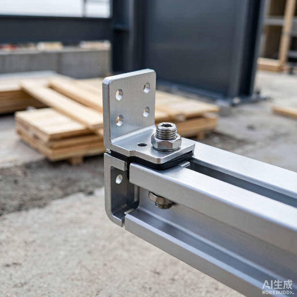
The connection hardware is the part most aluminium solar mounting profile suppliers ignore. It is also the part that decides whether the array survives twenty winters.
Stainless steel A2-70 bolts are the default for module-to-rail and rail-to-leg. They pair acceptably with 6063 T5 aluminium when the joint stays dry. Where rain or condensation can collect, step up to A4-80 marine grade or use a nylon isolation washer. Otherwise the galvanic couple between the two metals will eat the aluminium faster than either alone would have aged.
Module frame earthing uses a stainless steel bonding clip or a tin-plated copper lug with a self-drilling screw into the rail. UL 2703 requires the bonding to be tested as a system, not just per component. When the rail is AA20 anodised, the bonding screw has to bite through the anodised layer to land on bare metal. We torque these to 8 N·m and pull-test every fifth fastener during inspection.
On tracker torque tubes, the drive bearing seats on a 6061 T6 aluminium boss welded or bolted to the post. We have seen torque tube failures from under-spec bosses that were as cheap as the tube itself. Insist on the same alloy you used for the structural member. For a wider treatment of structural connections across all our industrial aluminium profiles, see our industrial aluminium profile product page.
11. Eight Buyer Pitfalls Before You Sign the PO
- Quoting by alloy alone. A cheap aluminium solar mounting profile quote that does not specify temper, wall thickness, tolerance grade and surface thickness is not a quote. Ask for the four numbers in writing.
- Ignoring die origin. A new die costs USD 800 to USD 1,800 depending on size. A worn die produces underspec walls within a few thousand metres. Ask how many tonnes the die has produced.
- Skipping the test report. A tensile test certificate costs the supplier a few hundred RMB per batch. If they cannot produce one, the heat treatment was probably skipped.
- Trusting catalog pictures. Pictures show the finish, not the wall thickness. Demand a cross-section photograph at the critical clamp interface.
- Confusing anodising grade. AA10 is a cosmetic finish for indoor products. It does not belong on a rail. Insist on AA15 minimum, AA20 for outdoor service.
- Neglecting packaging. A rail that arrives scratched at the clamp seat is contaminated and hard to clean. Specify foam separators between layers in the crate.
- No load calculation. If the supplier cannot show you the EN 1991 or ASCE 7-22 calculation for your specific site coordinates and roof pitch, the structural check on the aluminium solar mounting profile has not been done.
- No UL 2703 listing. Selling into the US without the listing is a warranty and a liability issue. Confirm the system is on UL Product iQ before you accept it.
12. NA-VIEW Solar Mounting Profile Capabilities
Extrusion, alloys and finishing
NA-VIEW has supplied aluminium solar mounting profile to module makers, EPC contractors and racking system integrators across 30+ countries for more than eight years. Our Foshan factory runs six dedicated extrusion lines, with two reserved for solar profile supply to keep lead times short when demand spikes. Output is 500+ profiles per day at plus/minus 0.5 mm dimensional accuracy across the full 6,000 mm run.
Alloys we hold in regular production for the solar segment include 6063 T5 for rails and clamps, 6005 T5 for commercial rail and beam, and 6061 T6 for tracker torque tubes and heavy structural posts. Anodising is in-house on a 12,000 m² vertical line rated to AA25, so every aluminium solar mounting profile can be finished without leaving the plant. Powder coating and PVDF topcoat are available on a separate horizontal line with full pretreatment.
Engineering support, sampling and order terms
Engineering support is built into every aluminium solar mounting profile quote. Send us the project location, roof pitch, module size and design wind and snow values, and we will return a complete rail section proposal — alloy, temper, wall thickness, surface finish, fastener spec and indicative EN 1991 or ASCE 7 load combination — within seven working days. We can also work from your drawing if you already have an aluminium solar mounting profile you want matched.
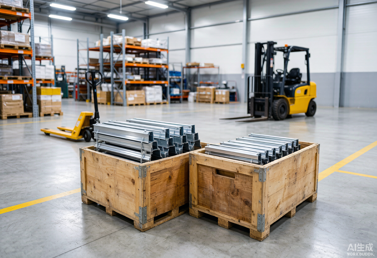
Sample lead time is three working days from an approved drawing, free for serious project orders. Trial order minimum is one 20-foot container. Standard production lead time on an aluminium solar mounting profile runs 25 to 28 days for an existing die, or 35 to 42 days for a new die. We accept T/T, L/C at sight and PayPal for samples and small trial orders. Shipping is FOB Shenzhen, CIF or DDP via the major European, Middle East and US ports. Every aluminium solar mounting profile shipment is packed in wooden crates with foam separators, EPE humidity indicators and printed OEM batch labels per the packaging spec you can download on our industrial aluminium profile page.
For an end-to-end look at how a custom aluminium section is developed from drawing to anodised rail, our extrusion process guide walks through die design, quenching and stretch-straightening step by step.
13. Frequently Asked Questions
What wall thickness should an aluminium solar mounting rail have for a 60-cell residential rooftop array?
For a typical 30-cell or 60-cell module pair on a low-slope residential roof in a temperate zone, we hold the rail wall at a minimum of 1.6 mm with a 2.0 mm average in the load-bearing flange. In typhoon-coastal or high-altitude snow regions we step the same rail to 2.0 mm minimum, sometimes 2.5 mm at the clamp interface. Anything under 1.4 mm on a residential rail is a cost-engineering red flag.
Which alloy is better for solar mounting profiles, 6063 T5 or 6005 T5?
Both work for residential rails and clamps. We default to 6063 T5 for the rail, mid-clamp, end-clamp and any visible cosmetic parts of an aluminium solar mounting profile, because the T5 temper gives a cleaner anodised surface. For ground-mount beams, structural legs and tracker torque tubes, we move to 6005 T5 or 6061 T6 because the higher tensile strength lets the section carry the same load in a thinner profile. The rule of thumb is simple: cosmetic and rail at 6063 T5, structural and large-span at 6005 T5 or 6061 T6.
How long does an anodised aluminium solar mounting profile last outdoors?
AA20 anodising at 20 micron thickness will outlast a 25-year design life in C3 and most C4 corrosion zones with only minor surface oxidation, which is why it remains our default finish for any aluminium solar mounting profile shipped to coastal Europe. In coastal C5 environments we recommend AA25 plus a clear PVDF topcoat or specified aluminium-zinc fasteners. We also publish a separate 1000-hour ASTM B117 salt-spray test report on request for any batch we run.
What payment terms does NA-VIEW accept for solar mounting profile orders?
Standard payment is 30 percent T/T deposit with the balance against a copy of the B/L. For trial orders under 5,000 USD we accept PayPal or full T/T in advance. For repeat buyers we can issue a 30 percent deposit with L/C at sight, and for contracts above 100,000 USD we can quote open-account terms on request. We bank through Bank of China and accept USD, EUR and RMB.
What is the typical production lead time for a custom aluminium solar mounting profile?
Standard production runs on existing dies take 25 to 28 days from PO to container loading. Custom die development for a new section adds another 10 to 14 days for die manufacture and a sample run. For urgent projects we hold a stocked inventory of common rails, mid-clamps and end-clamps in 6,000 mm lengths that can ship in 7 to 10 days. Sample extrusion from an existing die is dispatched within 3 days of drawing approval.
How does NA-VIEW pack aluminium solar mounting profiles for export?
Standard export packing is a wooden crate with EPE foam separators between each rail to prevent surface scuffing during container roll. Each crate carries a pearl-cotton humidity indicator and a stretch-wrapped outer skin. Profiles over 6 m are packed on reinforced steel racks that fit a 40-foot HQ container. Carton labels show the OEM batch number, profile code, length, quantity and bar code. Custom packaging including printed cartons and palletisation is available on request.
Request a Quote for Aluminium Solar Mounting Profile
Send us the module datasheet, project location, tilt angle, design wind and ground snow values, and we will return a complete aluminium solar mounting profile proposal — rail and clamp sections with calculated load combinations, alloy, wall thickness and surface finish — within seven working days. Free samples ship in three days on existing dies. NA-VIEW replies to every RFQ within 24 hours and supports T/T, L/C and PayPal for samples and trial orders, with FOB, CIF or DDP shipping on production runs.
Get a quote for aluminium solar mounting profile or email sales@naviewaluminium.com with your project brief.
Tags: aluminium solar mounting profile, solar PV mounting structure, AA20 anodised solar rail, 6005 T5 solar rail, EN 1991 solar load case, UL 2703 mounting system, ISO 9001 factory
CONTACT US


Foshan Naview New Building Materials Co., Ltd.
We are always here offering customers our reliable products and service.
If you want to liaise with us now, please click contact us